Build a customized fluorescent lamp system (T5)
When growing seedlings and plants in the vegetative stage using fluorescents is a great way to provide the beloved plants with bright and balanced light. This guide shows how to build a system that will fit for almost any growing needs indoors.
Introduction
Fluorescent lamp systems are used in gardening where it is crucial that the lamp is not emitting excessive heat. For example in restricted growchambers or where he temperature is already high and can not be conditioned down. Furthermore ue to the relatively low heat emission of fluorescents the lamps can be laced pretty close to the plant tops without burning tender tips.
The general usage of electricity and conversion to light is excellent with fluorescents. While the lightoutput of fluorescents really is well balanced between cost and usability the setup of a system that can be used for a whole chili-season is in my opinion not worth the harvest. If planned to go completely indoor for the whole season then ahigh pressure metal-vapor lamp like the Son-T is needed for the fruiting stage since the light from fluorescents will not penetrate the upper layers of foliage enough and generally will not be enough for a proper ripening process. But one of the best choices for the seedling and vegetative growth stage n the first three to four month still is a fluorescent setup.
T5 – The new king of the hill
Almost all fluorescent systems in use today use the standard T8 fluorescents. A telltale sign for T8 is the diameter of 26mm. While T8 still has a very good lightoutput for spent electricity they
do suffer from several drawbacks like flickering in convential setups (“cold” ballasts with starters) or selfshading due to the relatively thick bulb. Convential setups are those found in lowcost all-in-one cheap solutions found in hardware stores. Their fixture contains next to the sockets for holding the bulbs also the starter and the ballast.
Normal operation of those systems are flickering when turning on and also a distinctive humming of the ballast while operating. Especially the humming can be quite annoying with growing setups located in apartments.
Also the flickering is drawing on the longevity of the bulbs – not a costfactor when using the cheap bulbs but almost certainly a concern when using more expensive bulbs that emit the lovely spectrum necessary for healthy plants. More on lightspectrum and lamptypes later on.
The solution to the drawbacks of mentioned setups comes in the form of the “new” T5 fluorescent systems. T5 works on the same principle as T8 does – laying a current on a tube filled with gas causing discharges that emit light. But T5 are of newer design and are thin in comparison to T8 – they are 16mm in diameter. They emit more light in comparison to T8 for used electricity due to less self-shading and also less loss of spent energy from excessive heat. A turndown for existing systems is that T5 is not compatible with T8 and exclusively need relatively expensive electrical ballasts. But on the other hand they don’t need starters anymore and switch on immediately without the annyoing flickering. That goes also for the end of their lifespan – they simply switch off in contrast to conventional T8 setups which flicker heavily and can disturb plants with that for sure. Even if it is possible to substitue conventional starter and conventional ballast setups in T8 systems with an electronic ballast why not take up the opportunity and switch also to the superior slim T5 tube?
In general T5 emits more light than T8 with same wattage, uses simultaneously less energy and does not flicker which can be stressful on the eyes and cause headaches. Those of you who have been working under cheap fluorescents for extended periods of time know about that – headaches and fatigue at the end of the day. Citing the longer life of the bulbs an energy savings in general also makes up in the long run for the high price of electrical ballasts – especially with the rising energy bills in the last couple of years.
Types of bulbs
As with T8 T5 bulbs come in different choices – Normal, High Efficiency (HE) , High Output (HO) and Very High Output (VHO) as well as different wattages. For the old T8 systemswattages also meant the length of the tubes.
This is now also different since the introduction of the different types mentioned before. Of course HE, VHO and HO being “special” cost a little extra but are in my opinion well worth it.
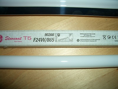
For growing I chose HO since the operating cost for VHO easily triple in energy investment – better to add more HO in my opinion. Still the comparison between T5 and T8 still holds when observing energy to lumen conversion. Staying with one type of tube the relationship between length and wattage is true again. But of course complicated is never complicated enough – so now we introduce “light color”. While light intensity is measured in “lumen” the color of light is measured in Kelvin, normally used to measure heat. The usual types of fluorescent light sources used for growing plants are in the range of 6000K. The best spectrum is about 6500K with a natural balance of red and blue. This is reflected on the fluorescent tube types with a three-digit code (three-band fluorescents). The best spectrum with the most usable light for plants is emitted from the tube type 865 – emitting light of 6500K mentioned before (Type 865 will be valid for manufacturers Philips, Osram, Sylvania and GE).
Here we have an extremely good balance of light in the spectrum of red and blue – the only colors realy needed for healthyplants.
For a comparison of light temperatures
- Normal office fluorescent 4000K
- Early morning/late afternoon sun 5000K
- Cloudy sky 6000K
- Bright blue summer sky 12000K-15000K
Green light is completely reflected by plants and thats simply why plants appear mostly green to us.
And as a side note to all the “special” tubes advertised for great growing conditions for example the GRO-Lux – they are too expensive and even while they emit “good” usable light they emit less than standard ones in terms of lumen and have a shorter lifespan.
The 865 type tubes sold are great from the light types and as well as unbeatable in energy to light conversion with the proper ballast, eg more lumen with the same watts.
The ballast
As mentioned T5 system need exclusively electronical ballasts. They need no additional starters anymore though. If youre reading this if youre planning to do your own system like mine then the question arises on what ballast is needed for the choice of number of lamps and their wattage.
Usual electronic ballasts (EB) come with the choice of supporting either one tube or two tubes. To keep the costs of the still quite more expensive EB low I suggest a setup with an even number of tubes and get half of that number with EB that support two tubes. The two-tube EB don’t cost significantly more then the one-tubed versions.
Also some EB come with a variable watt-range so you’re not set with the exact supported tube you bought the EB initially for. In my case I got the Philips H-Performer II which supports two tubes from a range from 14W to 39W meaning if I decide to stack up on watts later on I will be able to support the long T5 tubes with only a slight modification of my setup.
The other manufacturer for EB in Europe is Osram. Since everything gets more modern you may also come across some EB types which support dimming. If you’re NOT a light or electrical technician I recommend to stay away from those since their setup rapidly increases in complexity – especially those meant to integrate into DALI systems (digital bus to control whole enviroments) are not meant for the casual hobby horticulturist 😉 .
At least some knowledge of electric circuitry and of precautions is mandatory for the following though. The circuit between EB and tubes is almost always printed right next to the jacks connecting to the tubes.
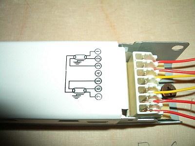
If you have never build a system like this before I strongly recommend to take the time to build a little test setup before you actually try to install the whole system in place. Also very important to note is the concept of “hot” wires.
Those are the wires in this case noted to connect to jacks number 1,2 and 6 and 7. Their corresponding jack number of your brand of EB must be printed somewhere on the EB. Most probably somewhere is printed “Keep wires x,y short” – so x and y are the hot wires.
Hot wires are the ones where most energy payload will go over. I have chosen in my setup to keep track of those with chosing to use exclusively red wires for those and also place the EB in that way that the red wires can be kept the shortest.
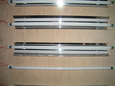
Reflectors
Tubes are round hence they emit light 360° and are wasting a lot of the energy invested in light output if the light is not reaching the plants. Now there are several solutions to that problem – some better some worse. You could of course try to keep cost minimal and just paint the area above the tubes with white paint. This will surely reflect some of the light but not the optimum percentage. In my opinion the only viable answer is to use reflectors like the ones used with metal-vapor lamps. Reflectors can’t be beaten in terms of light reflected – only maybe by polished mirrors. Some even say that reflectors can double the lumen reaching the plants. There are quite cheap reflectors around now for T5 tubes – I got mine surprisingly cheap at an aquaristic mailorder for just 8€ a piece. Those cheaper ones come with two clips with which they are directly clipped to the tube itself and can be turned some to reflect light more in a desired direction.
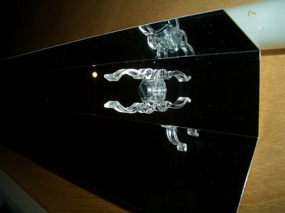
T5 Reflector and Clip
After assembling a reflector care should be taken to wipe away excessive fat stains on the reflector’s surface left from the fingers – thrust me, they are there even if you have not eaten a kebab while at work on the tubes.
Of course there is still the option to simply build your own reflectors. I have heard I it is a quite simple process if you happen to have access to sheets of reflective metal and quite some tools – scissors for cutting metal sheets, polishing machines and so on. I leave that up to you.
Also the growbox should be enclosed in reflective material to reflect that light rays that try to escape into your apartment. There are also several good and several bad choices. The worst is clearly aluminium foil which not only will wrinkle and therefore diffuse the light more than that it reflects but also will tear easily.
In my opinion the best is light-tight white plastic foil. This foil has a good reflective index and will not tear and also will be washable easily. If you happen to get hands only on very thin white plastic foil you may need to install that in double layers.
Wiring
The EB needs two kinds of wires. One is for connecting the EB to the general circuit of 220V (maybe different in some countries), the other is needed to connect the tubes to the EB. For the first a standard electrical wire is usable as long as it has three leads to connect also the grounding pins which is a must for wetroom constructions like a growing setup.
I highly recommend also a connector suitable for wetroom constructions. But beware not to use a too strong cable – the EB connectors I have seen just support single leads of up to 1mm! For the circuits between EB and tubes I have chosen bell wire with a diameter of 0.6mm and that comes one-leaded in a roll of about 10m. I got that in two colors to distinguish between hot and long wires – see section “Ballast” for an explanation of that.
Make sure not to chose a thinner wire since this will mean more resistance in the wire and more loss in terms of heat and less light. Read the information on your EB carefully on what type of wire they suggest to use. A good starting point may be the manufacturer’s website.
The homegrown lightsystem – The plan
So you have designated an area somewhere tostart up the chilis for the coming season. Now before running off to the hardware store a little planning should be done on how to maximise the use lighting components and at the same time to keep costs minimal.
It will begin with measuring up the area available and check what possibly can be installed.
As you already have learnt fluorescent tubes come in fixed wattages indicating their size – or was it the size that indicates the wattage? ,) Checking the manufacturer’s several websites you will notice that there are only four sizes for T5 HO – 24W with 549mm, 39W with 849mm, 54W with 1149mm and 80W with 1449mm. You will have to add roughly 10mm to 15mm on each side of the tube for the sockets.
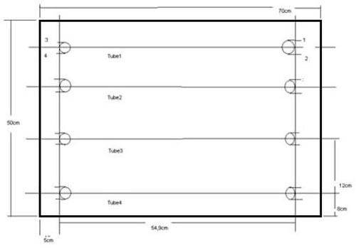
You should maximize the space available and choose the length that just so fits your space on the longest side. I have a growbox of 70cmx70cm so I am stuck with using 24W. But as you will experience that using T5 and reflectors this is more than enough for growing chilies.
Now for the spacing between the tubes. Placing tubes too close together is wasting a lot of potential. Why? First their emissions overlap and produce areas with not enough light and areas with too much. Second it makes it harder or even impossible to install reflectors – which should be separately installed for every single tube. Tubes don’t reflect light so the light from two tubes too close will be lost for the space between the tubes.
Notice the even spacing of the tubes. I chose to have a spacing between the tubes of about 12cm leaving me with 6 tubes of 24W.
Each tube will emit approximately 1900lm which will be up to 100% usable for the plants due to the reflectors. That gives me 11.400lm to blast upon an area of 0.49m². This is converted into Lux 23265Lx. Of course this is just shortly under the tubes – light intensity rapidly shrinks with a higher distance from the tubes. But again T5 will not heat up and the tubes can be hang just several cm above the highest shoots. I encourage you that if you have found the fitting setup then draw a plan so that you will have solid reference for later…this will save you many extra trips to the hardware store. A sample plan could look like the following:
The homegrown lightsystem – The components
In the following picture I have placed the components together that are needed to build up a six tube light system with each tube of type 24W HO – only thing missing is the board to mount everything on and the two rolls of bell wire.
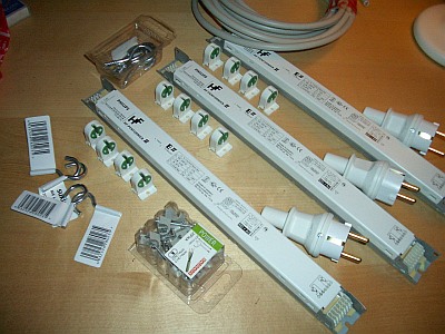
Components for a 6 tube 24W HO system
The complete list includes:
- 3x EB for 24W T5
- 12 T5 Sockets (G5)
- Hooks to hang the installation from ceiling
- Cable clippers for the heavy wires
- Bell wire, 10m each yellow and red
- Connectors for wetroom installations
- Heavy cable, 3-lead
- A wooden board to mount everything on
- Reflectors (not shown)
- and screws small enough to fight through holes of 1 and 2 as well as just long enough to give support on the board
Tools needed to put everything together:
- Screwdrivers
- Drill – drill bit must be small enough for screws not to lose support in the wood
- Hammer
- Hot-meld adhesive and “pistol”
- A foldable or extractable ruler
- A marker
- Currency tester (screwdriver-like with a light in the handle that shines on touch when electricity is present)
For the wooden board it is strongly recommended that the board is not too thin and of reliable quality. Especially flaky boards like the ones found in stuff from IKEA are completely unfit since they give no real support for screws more than once. Eg once drilled in it is not good to get them out again to make modifications since the hole will widen rapidly.1.5 to 2cm is ideal and
the board will be not too heavy even when of sturdy quality.
Remember to get screws not too long otherwise you maybe end up tighten up that “last” screw from one side that then by bad luck pierces through a tube or worse an EB.
So next to this also planning where to place the components before also is crucial.
All in all I have invested around 160 to 180€ in the whole setup but when I check the prices for simple 2 tubes setups at some stores I know that it is still unbeatable if the main concern is not on looks. Looking in aquaristic shops the kits for 2-tube systems alone including ballast and sockets usually start somewhere around 80€, completely assembled it is easy to invest double as much. Also I know that with some care the system will keep me happy at least the following two seasons without ever buying anything in addition. At last I expect the system to pay back some of the initial costs with the energy I save if I would use a conventional T8 or even worse on energy is a metal-vapor lamp.
The homegrown lightsystem – The Genesis
I started out thinking about the growing period and the changing needs for lighting.
I figured there will be not much light needed in the seedling stage and therefore switching on one EB with two tubes would be enough for the first few weeks to keep the plants bushy and short. I want to have the plants at this stage right in the center of my growbox so far away from the black foiled walls of what will become my flooding area eventually as possible. So it had to be the innermost two tubes lighting at first.
Then the plan is to start thinning out and place the survivors in individual cubes filling the area. So to even out the light in the box I would turn on the outermost lights in addition and so on. All this meant I would have to connect each pairs of tubes across the wiring for the other two pairs. This will have to be done at 90° angles according to the various information I could gather at OSRAM’s website. So far no problem. I assembled a tube with two sockets to have their combined length for later and measures the board as to place the tubes evenly spaced. I marked all the points were I later had to screw the sockets to.This is important for later measuring out the cable lenghts between tubes and EBs.
Then I figured I had to work on both sides of the board and both sides were certainly pretty sensitive to pressure since I decided to place the EB on the upper side of the board and the sockets with tubes on the other so no water could ever get to the precious EB.
I solved this by screwing in the hooks I intended to hang everything on later first and let them still stick out enough so they were higher than the EB and I safely could turn the boards without hurting the EB since the board would rest entirely on the four tips of the hooks.
I screwed the EB to the board and fit in the wiring to the main current. On my EB two ways are present to connect wires: One is to push the wires into a hole that snugs around the wire if it is thick enough and one to press the wire through a gap in a scissor-like structure which will cut in the wire slightly. Both require the isolation from the wire to be stripped for about 8mm. Then I secured the wires with cable clippers and plugged in check if the EB has juice on the tube circuits. Everything was fine so I unplugged and progressed to the task of the more complicated wiring between EB and tubes.
Check the circuit printed on the EB better three times and write down next to the connectors where each cable ultimately will go. Also label everything so you will always exactly know where each cable belongs. For example number the tubes and the EB – the connectors on the EB are already numbered. So when you have a cable named “1,1,3” you will know then that this cable belongs to EB1 and tube1 and goes to connector 3 on EB1. Of course feel free to invent your own system with what youre feeling more comfortable with.
Label the wires accordingly so when you turn the boards around you still know what cable is what. And make a plan on paper with the location of the EB and the corresponding tubes according to the EB printed circuit – better to write down these kinds of information one time too many than having a hassle later on trying to figure out why those damned tubes stay dead.
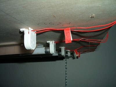
On the picture above you can see my way of labeling the wires. You can also witness what happens if you underestimate the might of the screw – had I hit something crucial with the screw protruding the wood in the front…could have been fatal if gone unnoticed.
Since I can not stand chaos with wires and the risks that arise if you do not keep good care of them I decided to lay them down I an ordered fashion. For that I use usually hot-meld adhesive that is molten in a pistol-like application. Also called hot-glue. I place a small drop of it everywhere I want the cable to stay tight.
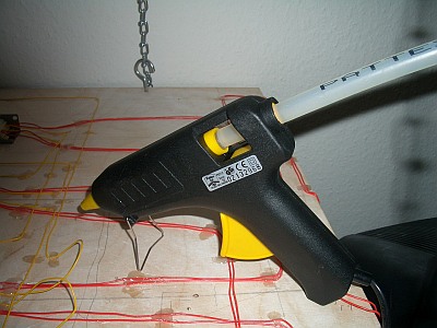
The final cabling then could look like the following picture:
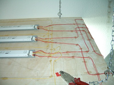
Admittedly it does not look as neat as the circuitry on a motherboard but the system lit up almost immediately after refitting a lose wire and has been tested as stable for two weeks a couple of hours each day right now.
Always always always check that the wires will have enough length that when turning to the other side they will be long enough to reach the socket-spots you have marked before. Better to leave them a little longer than trying to make them just right because as with the barber – shorter is always possible, the other way not. Anyway whats left now is to turn the board around and install the sockets finally.
From the previous steps you should already have marked out the final layout of your tubes and the wires coming from the EB should have enough length. Place the sockets on their spots and repeatedly check the wirelength to be just long enough to make a bend on the socket base and go up for about 1.5cm then cut the wire.
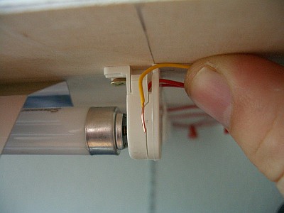
Better to check this twice and when unsure leave the wire slightly longer – again, you can not make the wire grow again. Tear off the isolation from the wire for about 5mm and gently insert them into the holes in the socket. Refer to your plan which wire will go in the upper part of the socket, which will go into the lower. Press the wire into the exit holes on the back of the
socket and gently screw the socket down.
After all sockets are screwn into place the magic moment has come…the final enlightment. If you have done everything right then go and get your sunglasses – but don’t fall down since you probaly have gone already blind. If some tubes or all don’t turn on don’t despair – just proceed to the next section – Troubleshooting.
The homegrown lightsystem – Troubleshooting
Damn, after all the work the system does not light up? Breath slowly a couple of times and then start to methodically debug it. For this you need a current tester – a device looking like a screwdriver with a light in the handle that shines when the tip touches electricity conducting material when the tip of the handle is also gently touched.
Do not be afraid with proper handling you can even touch the sockets in the wall with the tip of the tester without harm. But beware – if you feel unsure about anything of this and/or dont know what youre doing get someone to follow the list who does know it – electricity can and will kill you if it gets the chance.
Otherwise go through the following steps:
- Plug in the system. Check with the tester on the main circuit connectors if a current exists – No, unplug and check the sockets in the wall and also if maybe the main cable is broken or misconnected. Repeat with 1. Yes, proceed to 2.
- Check the connectors for the tube circuit if there is a current. The lamp in the tester will not burn as bright as with the main circuit since the current comming out of the EB is weaker but it still has to burn when everything is ok.Check for loosened cables in the EB.
- No, if 2. has passed then you will have to bite the sour apple and return the EB for another. Yes, proceed to 4.
- Make sure all systems are plugged out and loosen the screws from the sockets. Plug the system back in and check if there is power coming through the wire by sticking the tester in the free cableconnector spot in the base of the socket while handling only one socket at a time.Check if enough unisolated wire is connected in the socket. In case of a broken wire there is nothing else than to replace the wire completely.
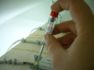
Checking the main cabling
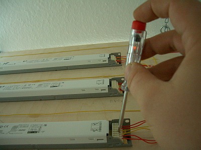
Checking tube circuits
Of course if you happen to have a electrical testing kit you can use that for checking on the conductivity of the wires.
Disclaimer
This guide has been put together with the best of my knowledge. I have done everything described here also on my own but since I am not a official electric engeneer I reject any responsibility in case someone plays around with electricity lighthearted. In any case if no basic understanding of electricity and it’s possible dangers is present I strongly encourage to consult someone who does.
Photos and Text: Serge Adamowsky